Stat-Ease Blog

Categories
The Do's and Don'ts for Screening Process Factors
Adapted from Mark Anderson's 2023 webinar, "Do's & Don'ts for Screening Process Factors."
Over the years working with process development engineers on scale-up and manufacturing troubleshooting, we've noticed a pattern: the factors that experts think drive their process are rarely the whole story. There are often other variables at play that nobody anticipates. The best way to uncover these is by using screening designs: broad, shallow experiments that help you uncover previously unknown factors. Done right, a well-designed screening study can transform your understanding of a process and point you directly to the vital few factors worth exploring in depth.
First, let’s make sure we understand what a screening design does in the overall arc of process optimization. Screening designs exist to help ensure we are working with the right factors in subsequent optimization studies. Figure 1 explains the overall strategy. Note that interactions – often the key to process improvement – are not identified until the subsequent step. But a good screening design can shed some light on whether or not there are interactions to further pursue.
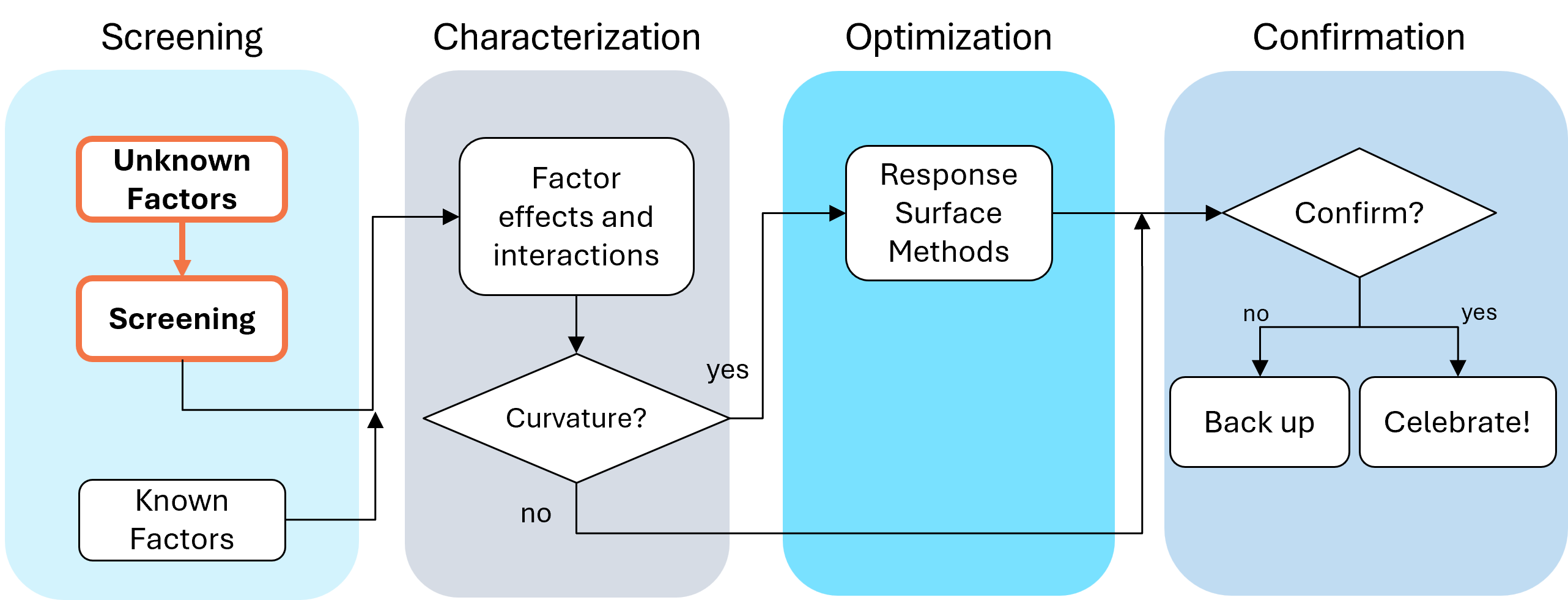
Fig. 1: Where screening fits in the SCOR strategy of experimentation.
With this strategy in view, here are the core do's and don'ts on screening designs. Consider this your field guide for avoiding the most common (and costly) mistakes.
DON'T: Include Factors You Already Know Will Affect the Process
This one surprises a lot of people, and has been the topic of heated discussions within our team. Why would you exclude a known important factor?
The answer is strategic focus and efficiency. By setting known factors aside during screening, you can concentrate on previously unknown factors: ones that might derail your process in unexpected ways. A broad and shallow two-level screening design lets you quickly identify the "vital few" from the "trivial many." In our experience, roughly 20% of factors you didn't expect to matter, matter! The known factors can be merged back in during the next phase of experimentation.
DON'T: Use Low Resolution Designs for Screening
This is our biggest pet peeve. Two types of designs fall into this trap: regular fractional factorials at Resolution III (shown as "red" designs in Stat-Ease software[MA3.1]), which alias main effects directly with two-factor interactions, and Plackett-Burman designs with even worse aliasing. That's a fatal flaw for screening, because if any factors interact (and in real processes, they often do) your main effect estimates are corrupted. You simply cannot trust what the analysis is telling you.
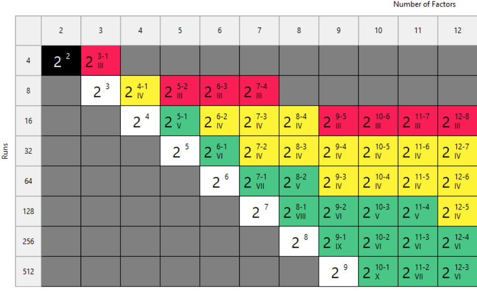
Fig. 2: Stat-Ease software's design picker, color-coded for your convenience.
We're particularly troubled by how often Plackett-Burman designs get recommended for screening. Even the NIST Engineering Statistics Handbook suggests using them, while simultaneously noting that “main effects are in general heavily confounded with two-factor interactions.” To us, that's an oxymoron. If main effects are confounded with two-factor interactions, how exactly is this a screening design? You can’t screen anything out!
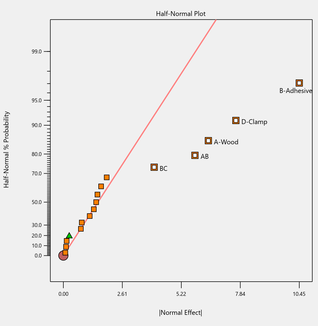
To illustrate the danger, we ran a simulation using the classic filtration rate dataset from Doug Montgomery's textbook Design and Analysis of Experiments. The full factorial result was clear: factors A (temperature), C (concentration), and D (stirring rate) were significant, along with strong AC and AD interactions.
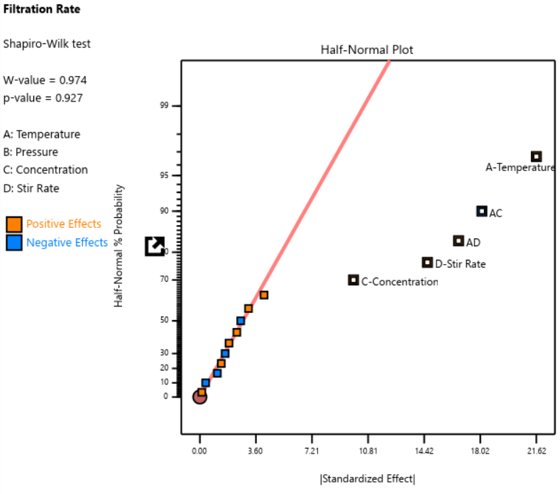
Fig. 3: Half-normal plot of effects for the full factorial design. Note that the selected effects are to well the right of the guideline.
When we re-ran the same underlying model through a 12-run Plackett-Burman simulation, the results were alarming. The AC and AD interactions got “smeared out” across multiple dummy factors. In particular, a fake factor E appeared significant when it was actually picking up aliased pieces of AC and AD. Meanwhile, the real main effect of D was undercut by its aliasing with one-third of AC, causing a cancellation. The result? Only factor A was correctly identified. Factors C and D were missed entirely.
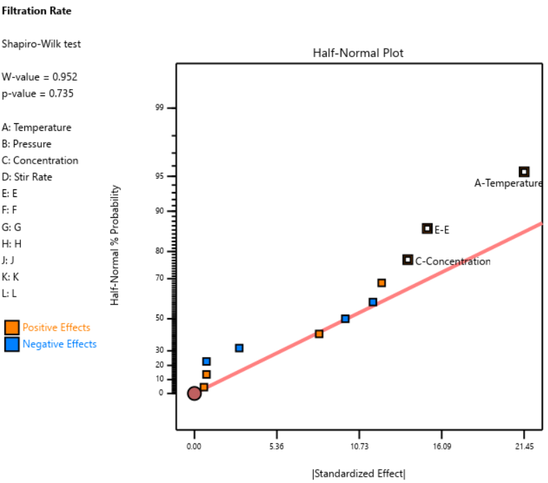
Fig. 4: Half-normal plot of effects for the Plackett-Burman design. None of the effects are to the right of the line, meaning this experiment shows no significant factors or interactions.
DOE pioneer George Box once said that running Resolution III or PB designs are "like kicking the TV to make it work." Sometimes you're desperate enough to try it, but there’s no guarantee you’ll get a usable result.
A Case Study in What NOT to Do
One of our users, a pharmaceutical process developer, sent in his design results hoping we could help salvage them. He had seven factors (time, temperature, and related process variables) and chose a Resolution III design with seven factors in eight runs. This is known as a ‘saturated’ design—the most factors that can be crammed into a given number of runs in a regular fractional factorial. Then, apparently recognizing the power would be low, he replicated the design, giving him 16 runs total, still at Resolution III.
As Ronald Fisher put it, a statistician is more like a pathologist than a medical doctor. We can tell you what killed the patient, but we can't bring it back to life. We wish this researcher had contacted us before running the design. The 16-run Resolution IV option for seven factors was right there in the software, highlighted in yellow (indicating a design more suitable for screening) It would have given him both the power and the resolution he needed. Instead, he replicated a bad design, which is a bit like making a photocopy of a photocopy.
The power calculations for these two designs are the clincher. One replicate of eight runs gave only 50% power to detect his specified signal-to-noise ratio of 1.67. Two replicates (still Resolution III) pushed that to about 87%: good power, terrible resolution. The unreplicated Resolution IV design in 16 runs also reached about 83% power, while giving him a design that could actually distinguish main effects from interactions.
DO: Start with a Resolution IV Design
As stated above, Resolution IV is the “Goldilocks” choice for screening. Main effects are aliased only with three-factor interactions, which are rarely active. That means that any significant main effects detected are almost certainly real. While two-factor interactions in a Res IV design may be murky, you'll know to investigate these further.
In Stat-Ease software, these are the yellow designs in the Regular Two-Level design builder. For up to eight factors, these medium resolution designs work beautifully. For nine or more factors, Stat-Ease’s proprietary, optimally templated, Minimum-Run screening design provides an excellent option when the standard design alternatives get too big.

Fig. 5: Min-Run Screening designs in Stat-Ease software. Choose them from the sidebar on the left.
Summary: The Screening Do's and Don'ts
To recap: hold known factors aside during screening and focus on the unknowns. Known factors will be studied together with the survivors of the screening design in the next round of experimentation when characterizing two-factor interactions with high-resolution designs. Avoid low-resolution designs: the red standard ones or Plackett-Burmans. Instead, go with medium Resolution IV or minimum run screening design from the start.
All Stat-Ease software licensees have access to our DOE experts. We encourage you to contact us before making a big mistake in your design of experiments. Don’t hesitate to reach out: do your screening right the first time.
Like the blog? Never miss a post - sign up for our blog post mailing list.
10 highly intelligent features that make the most from every experiment
Stat-Ease software provides powerful tools for design of experiments (DOE) with a great deal of intelligence baked in. Here are 10 “smart” features that make DOE easy for our users. From bottom to top (ordered by DOE phase: design, modeling, optimization, and confirmation), every one of them provides great value.
Here we go—the countdown begins!
- Factorial design-building wizard guides you to right-sized experiments via a ‘heads-up’ on power to detect important effects despite the variability of run, sample, and test.
- Optimal design builder’s exchange algorithm delivers a finely crafted experiment customized per your specifications.
- Preset lineup of near-zero effects on the half-normal graph of factorial effects makes it easy to see those that merit selection.
- Scoring system for polynomial models suggests just the right 'Goldilocks' level that does not underfit or overfit your results.
- Box-Cox plot studies your model residuals and recommends whether or not to apply a transformation for a better fit and advises which one will do best.
- Detection of non-hierarchical models and, if you agree to fix this, the needed terms get added back for a well-formulated polynomial.
- Application of a curvature test to two-level factorial designs with center points with advice on how to augment the design if significant.
- Annotations on statistical outputs that explain them in plain English and provide advice on what to do when they go awry.
- Numerical search using a highly effective variable-size simplex algorithm finds the most desirable combination of factor settings and/or component levels meeting all your goals for process efficiency, product efficacy, and cost reduction.
- Confirmation tool smartly updates the prediction interval based on the number of follow-up runs at your chosen setting.
Finally, one bonus feature in Stat-Ease software that will make you more intelligent: screen tips via the lightbulb icon (click the >> chevron if showing) next to the Help bubble. This will show interesting information about each feature on the screen for you to understand the underlying statistics.
Email me your favorite “they thought of everything” quality aspect of Stat-Ease software, and I will add it to my list for my next ‘shout out’ on intelligent features.
Thinking Outside the Box by Using Standard Error to Constrain Optimization
Response surface methods (RSM) pave the way to the pinnacle of process improvement. However, the central composite design (CCD)—the most common layout for RSM (pictured in Figure 1 for three factors)—traditionally limits the region of prediction to the cubical core. This conservative view avoids dangerous extrapolation out to the far reaches of the space defined by the axial ranges of the star points. This article lays out a less-limiting (but still reasonably safe) approach to optimization based on using a specified standard error (SE) of prediction as the boundary for searching out the optimal process setup.
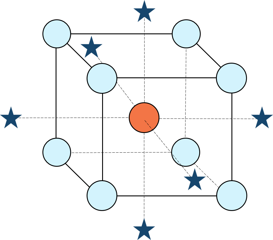
Figure 1: Central composite design for three factors
Three different methods for defining the search area will be detailed for a four-factor CCD. The goal is to avoid extrapolating beyond where the data provides adequate knowledge about the response while maximizing the volume that will be explored.
Let’s compare three boundaries for defining the search area in the factor space, the first two of which do not make use of the SE:
1. Factorial bounded—the hypercube* with vertices at coded values ±1, thus each edge spans 2 coded units. The volume of this four-dimensional hypercube is 16 (=2x2x2x2). The maximum SE is 0.764, which occurs at the vertices (i.e., corners). See figure 2. For comparison’s sake, we will use this SE (0.764) as our benchmark—anything more than this will be deemed unacceptable.
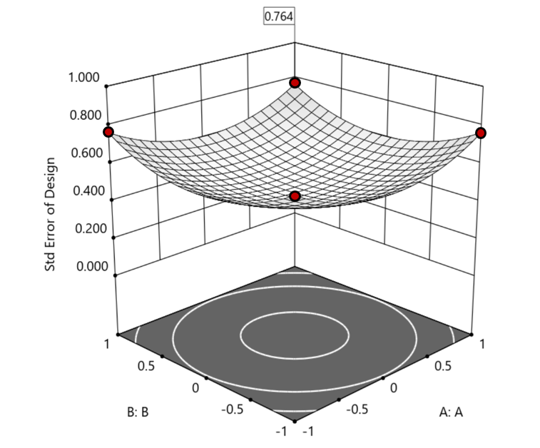
Figure 2. Looking only at the factorial region (±1), with factors C and D set to +1, we see that the highest SE values observed are at the factorial corners.
2. Axial (star-point) bounded—a cube with vertices at ±2 to include the star runs.
The volume of this four-dimensional hypercube is huge: 256 coded units (=4x4x4x4), which offers big advantages for optimization. However, most of the volume (69%) exhibits an SE ≥ 0.764 (maximum is 2.963!). Therefore, this method must be rejected. See figure 3.
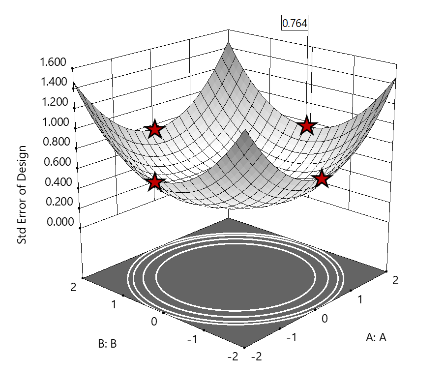
Figure 3. The default axial point placement is at ±2, which for 4 factors creates a rotatable design. The axial points therefore have the same SE as the factorial corner points—all are equidistant from the center. Note that factors C and D are set to zero (center) and the range for factors A and B are increased to ±2 to show the axial points.
3. Standard error bounded—the area within SE ≤0.764.*
Once again looking at figure 3, the SE at the axial (star) points equals that of the ±1 factorial points. Limiting the standard error ≤0.764 produces a hypersphere with a radius of 2. The volume of this hypersphere is 78.96, almost five times larger than the ±1 factorial hypercube.
Summarizing the three methods of defining the search area in the factor space:
- The factorial cube with vertices at ±1 may be too restrictive and may not include all the volume where acceptable predictions could be made.
- A cube with vertices at ±2 that includes the axial runs is too liberal; most of the volume has poor predictions.
- Defining the search area by standard error may prove insightful—it includes all the areas where acceptable predictions may reside.
Using standard error to constrain the optimization defines a search area that matches its properties:
- Spheres for rotatable CCDs. (Note: The above graphics and discussion assumed the choice of alpha values produced a spherical standard error plot).
- Cubes for face-centered CCDs.
- Irregular shapes for central composite designs with alpha between 1 and that recommended for rotatable designs, optimal designs, models for which model reduction was applied, and historical data.
An added bonus to using SE is that it adjusts the search area for reduced models and/or missing data.
It should be noted that it is assumed the design was sized for precision and contains enough data to make sound predictions within the cube (or hypercube). If the FDS is low (for example, below 80%), then making good predictions within the cube is already challenged. Extending the search zone outside the cube would exacerbate things further.
Another caveat is the assumption that a quadratic model pertains outside the design cube. The primary purpose of axial points in a central composite design is to fortify the estimates of quadratic terms to be applied within the cube. Sometimes the specified quadratic model performs well inside the cube, but extrapolation becomes dangerous due to higher-order behavior beyond the faces of the cube. Checking the diagnostic plots for anomalous behavior of the axial points can provide some assurance that the quadratic model is useful beyond the cube.
So, the key takeaway is this. Adding standard error to the search criteria and expanding the factor ranges beyond the edges of the factorial cube can be helpful for making judicious extrapolations beyond the edges of the cube. Simply applying the highest standard error found within the cube to regions outside the cube is a reasonable place to start, especially when the FDS performance of the design is over 80%. It is advisable to treat any interesting discoveries as tentative until verified by confirmation runs, augmented designs, or an entirely new design focused on the projected area of interest.
For more information on how to include standard error in the optimization module, see: Extrapolating a Response Surface Design in the Stat-Ease software Help menu.
*For 3 factors we can envision the factorial design space as a cube. With more than 3 factors (in this case 4 factors) we refer to the analogous region as a hypercube.
Acknowledgement: This post is an update of an article by Pat Whitcomb of the same title, published in the April 2017 STATeaser.
Like the blog? Never miss a post - sign up for our blog post mailing list.
Good Enough is Great: Why the Simpler Model Might Be Best
(Adapted from Mark Anderson’s 2023 webinar “Selecting a Most Useful Predictive Model”)
There can be a moment when analyzing your response surface method (RSM) experiment that you feel let down. You designed it carefully, maybe as a central composite design built specifically to capture curvature via a quadratic model, but when the results come in, the fit statistics tell you that a linear model fits just fine—no curves needed.
At this point you probably feel cheated. You paid for quadratic, but you only got linear. Now you have to recognize that's not a failure: that's the experiment doing its job.
Designed for Quadratic, Fitted with Less
When George Box and K.B. Wilson developed the central composite design back in 1951, they built it to estimate a full quadratic model: main effects, two-factor interactions, and squared terms that let you map response peaks, valleys, and saddle points. It's a powerful structure, and for many process optimization problems you'll need every bit of it. But not always.
Take a typical study with three factors: say, reaction time, temperature, and catalyst concentration; and two responses to optimize, for example, conversion (yield) and activity. Fit the conversion response, and the quadratic earns its keep. The squared terms are significant, and curvature is real. You get a rich surface to work with. Satisfying.
Then you turn to activity. You run through the same fitting sequence: check the mean, add linear terms, layer in two-factor interactions, and try the quadratic, but the data keeps saying “no thank you” at each step beyond linear. The sequential p-values tell a clear story: main effects matter, but the added complexity contributes nothing.
The right answer isn't to force a quadratic model because that's what you designed for. Use the linear model. That's what the data supports.
Simpler Models Are Easier to Trust
A more parsimonious model—statistician-speak for "simpler, with fewer unnecessary terms"—has real advantages beyond just passing significance tests. Every term you add raises the risk of overfitting: chasing noise instead of signal. A model stuffed with insignificant terms can look impressive on paper while quietly falling apart when you try to predict new results.
The major culprit for bloated models is the R-squared (R²) statistic that most scientists tout as a measure of how well they fitted their results. Unfortunately, R² in its raw form is a very poor quality-indicator for predictive models because it climbs whenever you add a term, regardless of whether it means anything. It is far better to use a more refined form of this statistic called “predicted” R², which estimates how well your model will perform on data it hasn't seen yet.
Trim the insignificant terms from a bloated model and you'll often see predicted R² go up, even as raw R² dips slightly. That's a good sign. For a good example of this counterintuitive behavior of R²s, check out this Stat-Ease software table showing the fit statistics on activity fit by quadratic versus linear models:
| Activity (quadratic) | Activity (linear) | |
|---|---|---|
| Std. Dev. | 1.08 | 0.9806 |
| Mean | 60.23 | 60.23 |
| C.V. % | 1.79 | 1.63 |
| R² | 0.9685 | 0.9564 |
| Adjusted R² | 0.9370 | 0.9477 |
| Predicted R² | 0.7696 | 0.9202 |
| Adeq Precision | 18.2044 | 29.2274 |
| Lack of Fit (p-values) | 0.3619 | 0.5197 |
By the way, if you have Stat-Ease software installed, you can easily reproduce these results by opening the Chemical Conversion tutorial data (accessible via program Help) and, via the [+] key on the Analysis branch, creating these alternative models. This is a great way to work out which model will be most useful. Don’t forget, all else equal, the simpler one is always best—easier to explain with fewer terms to tell a cleaner story.
Here's a guiding principle: if adjusted R² and predicted R² differ by more than 0.2, try reducing your model. Bringing those two statistics closer together is usually a sign you're moving in the right direction.
So, When Do You Stop Tweaking?
This is where a lot of practitioners get into trouble—not by underfitting, but by endlessly refitting. There's always another criterion to check, another comparison to agonize over. Beware of “paralysis by analysis”!
George Box said it well: all models are wrong, but some are useful. The goal isn't a perfect model. The goal is a useful one. Here's how you know when you’ve made a good choice:
Check adequate precision. This statistic measures signal-to-noise ratio: anything above 4 is generally good. Strong adequate precision alongside reasonable R² values usually means you have enough model to work with, even if lack of fit is technically significant. (Lack-of-fit can mislead you, particularly when center-point replicates are run by highly practiced hands who nail that standard condition every time, giving you an artificially tight estimate of pure error.)
Look at your diagnostics, but don't over-interpret them. The top three are the normal plot of residuals, residuals-versus-run, and the Box-Cox plot for potential transformations. On the normal plot, apply the “fat pencil” test: if you can cover the points with a broad marker held along the line, you're fine. You're looking for a dramatic S-shape or an obvious outlier, not minor wobbles.
Try the algorithmic reduction, then compare. Stat-Ease software offers automatic model reduction tools. Run it, compare the reduced model to the full model on predicted R² and adequate precision, and make a judgment call. If the statistics are similar and the model is simpler, take it.
Then press ahead. Once you've checked your fit statistics, run your diagnostics, and done a sensible reduction, go use the model! You can always get a second opinion (Stat-Ease users can request one from our StatHelp team), but at some point the model is good enough. That's the whole point.
The Liberating Truth
There's something freeing about accepting a linear model from an experiment designed for a quadratic. It means your process is well-behaved in that region, easy to interpret and likely to predict well. Now you can get on with finding the conditions that meet your experimental goals—a process that hits the sweet spot for quality and cost at robust operating conditions.
The experiment isn't a failure when it gives you something simpler than expected. It's doing exactly what a good experiment should do: telling you the truth.
Like the blog? Never miss a post - sign up for our blog post mailing list.
Hear Ye, Hear Ye: A Response Surface Method (RSM) Experiment on Sound Produces Surprising Results
A few years ago, while evaluating our training facility in Minneapolis, I came up with a fun experiment that demonstrates a great application of RSM for process optimization. It involves how sound travels to our students as a function of where they sit. The inspiration for this experiment came from a presentation by Tom Burns of Starkey Labs to our 5th European DOE User Meeting. As I reported in our September 2014 Stat-Teaser, Tom put RSM to good use for optimizing hearing aids.
Background
Classroom acoustics affect speech intelligibility and thus the quality of education. The sound intensity from a point source decays rapidly by distance according to the inverse square law. However, reflections and reverberations create variations by location for each student—some good (e.g., the Whispering Gallery at Chicago Museum of Science and Industry—a very delightful place to visit, preferably with young people in tow), but for others bad (e.g., echoing). Furthermore, it can be expected to change quite a bit from being empty versus fully occupied. (Our then-IT guy Mike, who moonlights as a sound-system tech, called these—the audience, that is—“meat baffles”.)
Sound is measured on a logarithmic scale called “decibels” (dB). The dBA adjusts for varying sensitivities of the human ear.
Frequency is another aspect of sound that must be taken into account for acoustics. According to Wikipedia, the typical adult male speaks at a fundamental frequency from 85 to 180 Hz. The range for a typical adult female is from 165 to 255 Hz.
Procedure

Stat-Ease training room at one of our old headquarters—sound test points spotted by yellow cups.
This experiment sampled sound on a 3x3 grid from left to right (L-R, coded -1 to +1) and front to back (F-B, -1 to +1)—see a picture of the training room above for location—according to a randomized RSM test plan. A quadratic model was fitted to the data, with its predictions then mapped to provide a picture of how sound travels in the classroom. The goal was to provide acoustics that deliver just enough loudness to those at the back without blasting the students sitting up front.
Using sticky notes as markers (labeled by coordinates), I laid out the grid in the Stat-Ease training room across the first 3 double-wide-table rows (4th row excluded) in two blocks:
- 2² factorial (square perimeter points) with 2 center points (CPs).
- Remainder of the 32 design (mid-points of edges) with 2 additional CPs.
I generated sound from the Online Tone Generator at 170 hertz—a frequency chosen to simulate voice at the overlap of male (lower) vs female ranges. Other settings were left at their defaults: mid-volume, sine wave. The sound was amplified by twin Dell 6-watt Harman-Kardon multimedia speakers, circa 1990s. They do not build them like this anymore 😉 These speakers reside on a counter up front—spaced about a foot apart. I measured sound intensity on the dBA scale with a GoerTek Digital Mini Sound Pressure Level Meter (~$18 via Amazon).
Results
I generated my experiment via the Response Surface tab in Design-Expert® software (this 3³ design shows up under "Miscellaneous" as Type "3-level factorial"). Via various manipulations of the layout (not too difficult), I divided the runs into the two blocks, within which I re-randomized the order. See the results tabulated below.
| Block | Run | Space Type | Coordinate (A: L-R) | Coordinate (B: F-B) | Sound (dBA) |
|---|---|---|---|---|---|
| 1 | 1 | Factorial | -1 | 1 | 70 |
| 1 | 2 | Center | 0 | 0 | 58 |
| 1 | 3 | Factorial | 1 | -1 | 73.3 |
| 1 | 4 | Factorial | 1 | 1 | 62 |
| 1 | 5 | Center | 0 | 0 | 58.3 |
| 1 | 6 | Factorial | -1 | -1 | 71.4 |
| 1 | 7 | Center | 0 | 0 | 58 |
| 2 | 8 | CentEdge | -1 | 0 | 64.5 |
| 2 | 9 | Center | 0 | 0 | 58.2 |
| 2 | 10 | CentEdge | 0 | 1 | 61.8 |
| 2 | 11 | CentEdge | 0 | -1 | 69.6 |
| 2 | 12 | Center | 0 | 0 | 57.5 |
| 2 | 13 | CentEdge | 1 | 0 | 60.5 |
Notice that the readings at the center are consistently lower than around the edge of the three-table space. So, not surprisingly, the factorial model based on block 1 exhibits significant curvature (p<0.0001). That leads to making use of the second block of runs to fill out the RSM design in order to fit the quadratic model. I was hoping things would play out like this to provide a teaching point in our DOESH class—the value of an iterative strategy of experimentation.
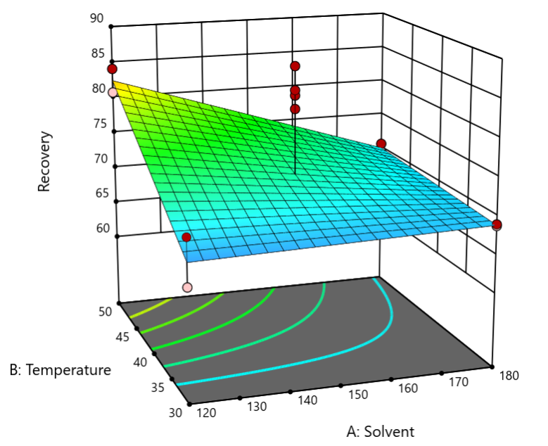
The 3D surface graph shown below illustrates the unexpected dampening (cancelling?) of sound at the middle of our Stat-Ease training room.
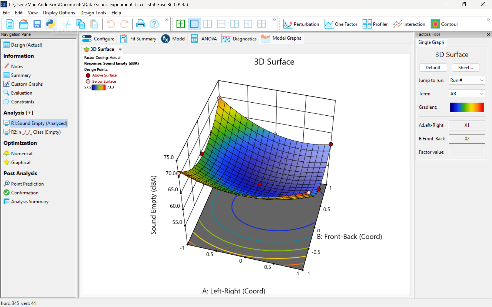
3D surface graph of sound by classroom coordinate.
Perhaps this sound ‘map’ is typical of most classrooms. I suppose that it could be counteracted by putting acoustic reflectors overhead. However, the minimum loudness of 57.4 (found via numeric optimization and flagged over the surface pictured) is very audible by my reckoning (having sat in that position when measuring the dBA). It falls within the green zone for OSHA’s decibel scale, as does the maximum of 73.6 dBA, so all is good.
What next
The results documented here came from an empty classroom. I would like to do it again with students (aka meat baffles) present. I wonder how that will affect the sound map. Of course, many other factors could be tested. For example, Rachel from our Front Office team suggested I try elevating the speakers. Another issue is the frequency of sound emitted. Furthermore, the oscillation can be varied—sine, square, triangle and sawtooth waves could be tried. Other types of speakers would surely make a big difference.
What else can you think of to experiment on for sound measurement? Let me know.
Like the blog? Never miss a post - sign up for our blog post mailing list.